Liddell Company, Manufacturers of Engines,
Boilers, Saw Mills, Cotton and Yarn Presses, Shafting,
Pulleys, etc., Charlotte, N.C.:
Electronic Edition.
Liddell and Co. (Charlotte, N.C.)
Funding from the Institute for Museum and Library Services supported the electronic publication of this title.
Text transcribed by
Apex Data Services, Inc.
Images scanned by
Melissa Meeks
Text encoded by
Apex Data Services, Inc. and Melissa Meeks
First edition, 2002
ca. 75K
Academic Affairs Library, UNC-CH
University of North Carolina at Chapel Hill,
2002.

Source Description:
(cover) Liddell Company, Charlotte, N.C.
(title page) Liddell Company, Manufacturers of Engines, Boilers, Saw Mills, Cotton and Yarn Presses, Shafting, Pulleys, etc., Charlotte, N.C.
Liddell and Co. (Charlotte, N.C.)
[44] p., ill.
Charlotte, N. C.:
Hirst Printing Company
1890.
Call number VCp672 L71 L (North Carolina Collection, University of North Carolina at Chapel Hill)
The electronic edition is a part of the UNC-CH
digitization project, Documenting the American South.
The text has been entered using double-keying and verified against the original.
The text has been encoded using the recommendations for Level 4 of the TEI in Libraries Guidelines.
Original grammar, punctuation, and spelling have been preserved. Encountered
typographical errors have been preserved, and appear in red type.
Any hyphens occurring in line breaks have been
removed, and the trailing part of a word has been joined to
the preceding line.
All quotation marks, em dashes and ampersand have been transcribed as
entity references.
All double right and left quotation marks are encoded as " and "
respectively.
All single right and left quotation marks are encoded as ' and ' respectively.
All em dashes are encoded as --
Indentation in lines has not been preserved.
Spell-check and verification made against printed text using Author/Editor (SoftQuad) and Microsoft Word spell check programs.
Library of Congress Subject Headings
Languages Used:
- English
LC Subject Headings:
- Liddell and Co. (Charlotte, N.C.) -- Catalogs.
- Cotton machinery -- North Carolina -- Charlotte.
- Cotton machinery -- Design and construction.
- Manufactures -- North Carolina -- Charlotte.
- Foundries -- North Carolina -- Charlotte.
Revision History:
- 2003-03-10,
Celine Noel and Wanda Gunther
revised TEIHeader and created catalog record for the electronic edition.
-
2002-12-10,
Melissa Meeks
finished TEI-conformant encoding and final proofing.
-
2001-10-29,
Melissa Meeks
finished TEI/SGML encoding
- 2001-10-15,
Apex Data Services, Inc.
finished transcribing the text.
[Cover Page Image]
[Title Page Image]
LIDDELL COMPANY
MANUFACTURERS OF
Engines, Boilers, Saw Mills,
COTTON AND YARN PRESSES.
SHAFTING, PULLEYS, Etc.
CHARLOTTE, N. C.
CHARLOTTE, N. C.:
HIRST PRINTING COMPANY, 212 EAST TRADE STREET.
1890.
Page 1
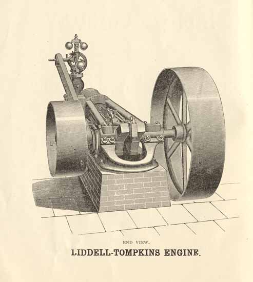
END VIEW.
LIDDELL-TOMPKINS ENGINE.
Page 2
The Liddell-Tompkins Engine.
We present in this circular two views of the Lidell-Tompkins Engine, and desire to call particular attention to the design, which is based on a long and varied experience in engine building and a thorough examination of the latest improvements in that line. It will be noticed that the line of strain is straight through the centre of the frame, having as much strength above as below it, thus avoiding all inclination to spring.
Everything about this engine is free from any complications. It is especially adapted and built with a view to an increase of speed, thereby increasing the power over other slide valve engines in general use. The piston and valve rods are of steel and the crank is a solid forging slotted. The governor used is accurate and has a speeding attachment and safety stop.
Each engine is balanced and tested before leaving our works.
We manufacture six sizes of these engines, varying in power from twelve to forty horse, as indicated in specifications.
We invite a careful examination of the cuts and specifications.
Page 3
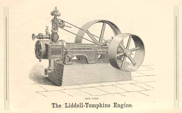
SIDE VIEW.
The Liddell-Tompkins Engine.
Page 4
Specifications of the Liddell-Tompkins Engine.
| NUMBER OF SIZE. | 0 | 1 | 2 | 3 | 4 | 5 |
| Number of revolutions | 200-250 | 200-250 | 175-225 | 175-225 | 175-225 | 175-225 |
| Horse power as usually rated | 12-15 | 15-20 | 20-25 | 25-30 | 30-35 | 35-40 |
| Diameter of cylinder and length of stroke | 7 × 10 | 8½ × 10 | 9 × 12 | 10 × 12 | 11-12 | 12 × 12 |
| Diameter of Steam pipe | 1½ in. | 2 in. | 2 in. | 2½ in. | 2½ in. | 2½ in. |
| Diameter of Exhaust pipe | 2 in. | 2½ in. | 2½ in. | 3 in. | 3 in. | 3 in. |
| Diameter of Pulleys | 40-20 | 44-24 | 48-26 | 48-30 | 52-30 | 54-30 |
| Face of Pulleys | 8-8 | 12-10 | 12-10 | 12-12 | 14-12 | 14-12 |
| Diameter of Crank Shaft | 2¾ in | 3 in. | 3¼ in. | 3¼ in. | 3½ in. | 3¾ in. |
| Diameter of Wrist | 2¾ in. | 3 in. | 3¼ in. | 3¼ in. | 3½ in. | 3¾ in. |
| Length of Journals | 5-6 | 7-6 | 8½-6½ | 8½-6½ | 9¼-7¼ | 10-8 |
Fixtures comprise Governor, Governor Belt, Throttle Valve, Valve Lubricator, 2 Cylinder Cocks, 2 Oil Cups, Elbow and Nipple for exhaust, and nipple drilled for Valve Lubricator.
Foundation bolts, steam and exhaust pipes, and fittings are refurnished when desired at the ruling market prices.
Page 5
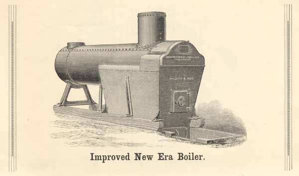
Improved New Era Boiler.
Page 6
The Improved New Era Boiler.
The New Era Boiler has been on the market over ten years, during which not less than 1,000 have been sold and put into, use, and experience has proven that they are not only the cheapest, but also the safest and most economical portable boiler in use. The principle of this boiler having been thoroughly established, we have removed the only objection that was ever made to it, and now present to the trade and our customers the Improved New Era.
The boiler is cylindrical in form, the upper half of the shell at the furnace end being extended to receive the front casting and form the combustion chamber. The furnace is formed by a plate of iron bolted to the boiler and closed at each end by suitable castings, in which are the door and draft openings. The sides of the furnace, front castings, sides and top of the combustion chamber are lined with fire bricks. The principal draft is at the rear end of the furnace, and the products of combustion pass forward into the combustion chamber and from there into the tubes.
In the old style New Era Boiler the bricks with which the furnace was lined were of special shapes and hard to obtain, except from the manufacturers. In the Improved New Era the furnace is lined with bricks of ordinary shapes, and the castings which hold them in position not being exposed to the heat of the furnace, seldom require to be renewed, but will last for years. And while we would always recommend the use of fire bricks, as they are more durable, they are not a necessity, as the lining may be renewed at any time and with very little trouble, with the ordinary clay bricks.
The weakest and most exposed parts of the ordinary portable boiler are the crown sheet and furnace sides. They require to be heavily stayed to resist the pressure; and although most exposed to the fire, are yet the parts most liable to injury, caused by low water or deposits of sediment. The first part exposed by low water is the crown sheet, which is at all times subjected to the greatest heat, and yet has always the least water to protect it. The sides of the furnace are ready receptacles for the deposit of mud and all impurities of the water, while the numerous stay bolts required to strengthen them make them the most difficult parts of the boiler to keep clean. As a result, the furnace of the portable boiler is the great source of danger and expense for repairs.
In the New Era these objections to the portable boiler are removed, while at the same time the elements of portability and convenience are fully retained. In this boiler we have no flat crown sheet, no furnace sides to fill with mud and burn out, no stay bolts, and but one seam exposed to the fire. Instead of having less water over the crown sheet than in any other part of the boiler, we there have more, and the effect of low water is not to expose the crown sheet, but the upper row of tubes, which may cause a leak, but not an explosion, and will not endanger life. The fire-brick lining in the sides, when worn out, is easily replaced at a trifling expense, and the great cost of repairs to which the ordinary portable boiler is subject is saved. Thus it will be seen that the greatest objections to the use of the portable boiler, viz., danger to life and expense for repairs, are removed.
Page 7
One great objection to the common form of Portable Boiler is that they are wasteful of fuel, and it is only their great convenience and portability that make them a favorite form of boiler. The waste of fuel is due mostly to defective combustion. When fresh fuel is thrown into the furnace a large share of the gases is set free at a low temperature and passes directly into the tubes, and out through the chimney unconsumed, and this continues till the fuel and gases are heated to the combustion point. Here is not only a heavy direct loss from waste of unconsumed gases, but also an indirect loss occasioned by deposits of soot in the tubes, thus impeding the draft and preventing the absorption of heat by the water through the tubes. The furnace sides in the ordinary Portable Boiler can get no hotter than the water contained in them--say 300 degrees, and of course do little toward promoting combustion in the furnace; while in the "New Era" Boiler, the lining of the furnace and combustion chamber being fire-brick, is soon raised to very high temperature--say 1,500 or 2,000 degrees, and when fresh fuel is thrown in the gases set free--instead of passing directly into the tubes and being wasted--must pass forward and into the combustion chamber, and from thence into the tubes; during all this time being surrounded and brought into immediate contact with the fire-brick at this high temperature, almost perfect combustion of the gases is attained, so that little or no smoke comes out of the stack. Thus great economy of fuel is the result, not only directly by the combustion of the gases that are unconsumed in the other styles of furnaces, but indirectly by lessening the deposit of soot in the tubes, and affording better draft and absorption.
Thus, any kind of fuel can be successfully used--a saw mill for instance, can be run all day on the green slabs just from the saw. The furnace is large, the heating and evaporating surfaces are large, and it combines with the safety of a stationary boiler the convenience and portability of a portable.
Specifications of the Improved New Era Boiler.
| NUMBER OF SIZE | 0 | 1 | 2 | 3 | 4 | 5 | 6 | 7 | 7½ | 8 |
| HORSE POWER. | 6 | 8 | 10 | 12 | 15 | 20 | 25 | 30 | 35 | 40 |
| Diameter of Boiler in inches | 26 | 28 | 28 | 30 | 30 | 34 | 34 | 36 | 40 | 44 |
| Length of Furnace in inches | 42 | 42 | 48 | 48 | 54 | 60 | 60 | 60 | 60 | 60 |
| Width of Furnace in inches | 22 | 24 | 24 | 26 | 26 | 30 | 30 | 32 | 36 | 40 |
| Number of tubes (all 3-inch) | 17 | 20 | 20 | 24 | 26 | 32 | 32 | 36 | 38 | 48 |
| Length of tubes in inches | 78 | 78 | 96 | 96 | 108 | 108 | 120 | 120 | 144 | 120 |
| Diameter of Stack in inches | 12 | 14 | 14 | 16 | 16 | 18 | 18 | 18 | 20 | 22 |
| Length of Stack in feet | 20 | 20 | 25 | 25 | 30 | 30 | 30 | 35 | 40 | 40 |
| Estimated Weight with fixtures | 3250 | 3700 | 4050 | 5050 | 5400 | 6050 | 6400 | 7550 | 8000 | 9000 |
Fixtures comprise Smoke Stack, Guy Wire (four times length of stack), Safety Valve, Gauge Cocks, Steam Gauge, Stop Valve, Blow off Valve, Check Valve, Whistle and Pipe.
Page 8
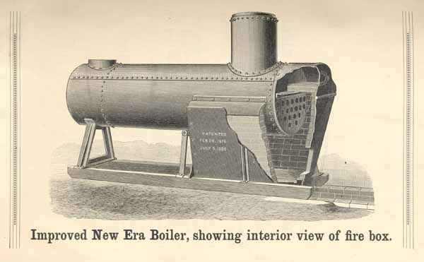
Improved New Era Boiler, showing interior view of fire box.
Page 9
Liddell's
Patent Variable Feed Saw Mills.
We wish to call your special attention to the LIDDELL PATENT VARIABLE FRICTION FEED SAW MILL, the only Variable Feed Mill awarded a medal of the First Class at the World's Exposition at New Orleans, for which we claim the following advantages:
1st--Feed instantly changed from FASTEST to SLOWEST at pleasure.
2d--Feed VARIABLE or FIXED, as desired.
3d--No strain on Mandrel to cause springing.
4th--No heating of saw from a hot journal box.
5th--20 to 30 per cent. greater capacity than other mills.
6th--BULL DOGS enabling the sawyer to cut the last board true, three-quarters of an inch thick.
7th--BULL DOGS clamp the board above and below. Operated by one lever.
8th--Ratchet Head Blocks and accurate Set Works.
9th--Four sizes built, ranging in capacity from 3,000 to 40,000 feet of lumber per day.
Page 10
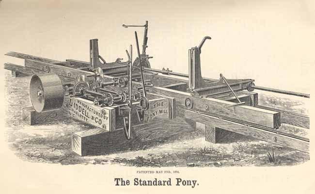
PATENTED MAY 27th, 1884.
The Standard Pony.
Page 11
The "Standard" Mills.
In these mills the disc or friction plate is attached to the mandrel and the power is taken from it by means of two frictions bearing upon opposite sides of the disc. By the use of a compound lever the friction wheels are moved to and from contact with the disc by a forward and backward movement of the perpendicular lever. The other lever, moving in the same direction, throws the feeding friction wheel across the face of the disc, the wheel sliding on a feather key. The backing friction, on the opposite side of the disc, will run in an opposite direction, and serves to back the carriage. This friction is made of suitable size to back the carriage at any desired speed, to suit the ideas of all sawyers, the adjustment being made by means of a set screw. The pressure on the disc necessary to operate the carriage is not against the mandrel, as is the case in the old style Mills, but is with its length, so that instead of being a drawback, disturbing the mandrel in its bearings, the tendency is to give the saw a lead into the log while the carriage is being fed to the saw and to throw the saw away from the log while the carriage is running back. Experience has shown that this actually takes place, the saw running clear of the log in its backward movement, and keeping the lumber free from scars.
Our Variable Feed Saw Mills give to the lumberman the advantages of an instant change from the fastest to the slowest rate of speed, or to any intermediate feed that may be required, by a single stroke of a lever. The great advantage of this will at once appear. It enables the sawyer to use his power to its fullest capacity at all times. When the logs are large and power light there need be no stopping of the carriage to allow the exhausted power to be recovered, as is so often done when small engines are used. The log can be fed to the saw so as to give the engine all it can do and no more, and thus also avoid the sudden jerks to which these engines are subjected. On the other hand, if the timber is light the small engine can be made to cut as fast as a large one on the old style mill. A gain of from twenty to thirty-five per cent. of cutting power is made. This is the verdict of sawyers and those who operate these mills.
The variation in the feed is made by moving a friction wheel from the centre to the periphery of a disc or plate, which is kept revolving when the mill is running. There are several ways of attaching this disc to the moving parts of the Mill, and we have patented and now manufacture two styles of Mills, so as to meet the different ideas of saw mill men, both of these styles being illustrated in this circular.
Our Standard Pony Mill. Detailed Specifications.--Husk 7 ft. long, 3 ft. wide, 10 in. deep and 3 in. thick; mandrel 2 3/16 in. diameter, forged collar, adjustable arbor boxes, wheel spreader, saw guide; width of carriage 2 ft. 3 in.; driving pulley 20 in. diam., 10 in. face; 20 ft. carriage, 40 ft. of track on portable stringers, two Patent Simultaneous Ratchet Head Blocks with Bull Dogs, 13 ft. of connecting shaft, swage, gauge, monkey wrench, cant hook and oil can. The PONY MILL will carry up to a 48-inch saw.
Our Standard Mill. Detailed Specifications.--Husk 9 ft. long, 4 ft. 4 in. wide, 12 in. deep and 4½ in. thick; mandrel 2 3/16 in. in diam., forged collar, pivoted adjustable arbor boxes, board roller, wheel spreader, and patent adjustable Saw Guide, two Patent Simultaneous and Independent Ratchet Head Blocks, with Bull Dogs and 17 feet of connecting shaft, swage, gauge, monkey wrench and oil can; driving pulley 20 in. diam., 13 in. face, 24 ft. carriage and 48 ft. of track on portable stringers, carriage 35½ in. wide, 4 in. thick, and 6½ in. deep; track 3¾ in. thick and 4¾ in. deep. The STANDARD MILL will carry up to a 54-inch saw.
Our Standard Mill No. 3. Detailed Specifications.--Husk 9 ft. 6 in. long, 5 ft. 7 in. wide, 12 in. deep and 4½ in thick; mandrel 2 15/16 in. in diameter, forged collar, pivoted adjustable arbor boxes, board roller, wheel spreader, 24 ft. of carriage and 48 ft. of track on portable stringers; patent adjustable Saw Guide, carriage 35½ in. wide, 4 in. thick and 6½ in. deep; track 3¾ in. thick and 4¾ in. deep; two Patent Simultaneous and Independent Ratchet Head Blocks, with Bull Dogs and 17 ft. of connecting shaft, driving pulley 20 in. diam., 13 in. face, swage, gauge, monkey wrench, cant hook and oil can.
The STANDARD MILL No. 3 will carry up to a 60-inch saw.
Our Standard Mill No. 4. Detailed Specifications.--Husk 9 ft. 6 in. long, 5 ft. 7 in. wide, 12 in. deep and 4½ in. thick; mandrel 3 3/16 in. diam., forged collar, patent adjustable saw guide, pivoted adjustable arbor boxes, board roller, wheel spreader, 24 ft. carriage, and 48 ft. of track on portable stringers, carriage 37½ in. wide, 5 in. thick, and 7 in. deep; track 5 in. thick and 5 in. deep; two heavy Patent Simultaneous and Independent Ratchet Head Blocks, with Bull Dogs and 17 ft. of connecting shaft, swage, gauge, monkey wrench, cant hook and oil can. The STANDARD MILL No. 4 will carry up to a 66-inch saw.
On the STANDARD MILL No. 3 and the STANDARD MILL No. 4 we place, if desired, at an extra cost, our Top Saw attachment.
All Bevel Gears are Made of Steel.
Page 12
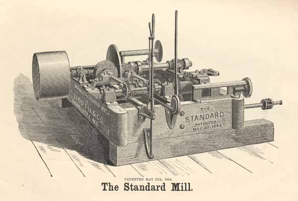
PATENTED MAY 27th, 1884.
The Standard Mill.
Page 13
PATENTED MARCH 27th, 1883.
The Clipper Mill.
Page 14
The "Clipper" Mill.
In this mill the power for feeding the carriage to the saw is taken from the mandrel by means of a mitre gear. This keeps the disc revolving as fast as the saw turns, and the friction wheel is moved across the face of the disc by a lever which is operated by the sawyer's knee, the friction wheels sliding on a feather key. The friction on the reverse side of the plate will, of course, move in an opposite direction, and by means of this the carriage is run back. This friction is made of such a size as will move the carriage back as rapidly as it is safe to move it, but the speed of this movement can be adjusted according to the ideas of each sawyer by means of a set screw.
In this mill, the power for feeding the carriage being taken from the mandrel by means of a gear attached as closely as possible to the bearing, the mandrel is not subjected to the sudden and violent pressure brought to bear upon it in the old style mills, and being less disturbed in its bearings will run truer and avoid the difficulties and annoyances of heated collars. To avoid the noise incident to iron gears running at a high rate of speed, we have made the one on the mandrel a mortise gear, the cogs being made of the best dry persimmon wood. The shaft to which the friction plate is attached runs in a solid iron frame (connected bearing) and is heavily shouldered, giving what is equivalent to four set collars on this shaft, as safeguard against wear and undue strain on the hubs of the friction plate and mitre gears.
The Improved Clipper Mill.
The cut on page 17 presents our Improved Clipper mill. While called the Improved Clipper it is in reality a combination of our Clipper and Standard mills, both of which are described in this catalogue and are well known to the trade.
In the Clipper mill the power for moving the carriage is transmitted from the mandrel by means of a gear, and the backward and forward motion of the carriage, and the variation in speed, is obtained from frictions operating on opposite sides of the disc.
In the Standard mill the disc is on the mandrel and the power is transmitted from it by frictions and two sets of bevel gears.
In the Improved Clipper mill there are two discs, one on the mandrel, and one at right angles to it, the power being conveyed by frictions,
Page 15
thus dispensing with all bevel gears. The disc is attached to the mandrel by means of a feather key, which prevents friction on the collar of the mandrel. The thrust of the disc from the main friction and the spring which holds it in its place, is against a babbitted face in the mandrel box. The mandrel is thus freed from any strain either against it or with its length. A lever is connected with the friction on the main disc, thus giving all the variations in feed obtainable in the Standard mill, while the other disc and frictions give all the variations in feed of the Clipper mill. The variations can thus be made at one or both places separately, or at the same time.
In this mill, therefore, we have an instant variation from a sixteenth of an inch feed to a four inch feed, and have accomplished this result without adding any complicated machinery, but, on the other hand, have actually dispensed with all bevel gears. In fact, we have combined in this mill the best features of the two Best Variable Feed Mills known, and have dispensed with the only objections that have ever been raised to either of them. The mill is, therefore, no experiment, having no features which are not in actual use on our mills in every State from Pennsylvania to Texas. The Special Award given it at the Augusta Exposition and the unusual attention and commendation it received while in active operation there, confirms our own estimate of its completeness.
As will appear from the detailed specifications given elsewhere, it is of the same size as the Standard and Clipper mills, and when sent out will have attached to it our well-known head blocks and bull dogs.
The advantages we claim for this mill not especially belonging to our other variable feed mills, consists of greater durability, a wider range of feed than heretofore given, and of a variation by lever in the gig-back.
SPECIFICATIONS OF CLIPPER AND IMPROVED CLIPPER
MILLS.
Husk, 9 ft. long, 4 ft. 4 in. wide, 12 in. deep, and 4½ in. thick; mandrel, 2 11/16 in. diameter, forged collar, pivoted adjustable arbor boxes, board roller, wheel spreader, patent adjustable saw guide; driving pulley 20 in. diameter and 13 in. face,; 24 ft. of carriage and 48 ft. of track on portable stringers; carriage, 35½ in. wide, 4 in. thick, and 6½ in. deep; track 3¾ in. thick and 4¾ in. deep; two Patent Simultaneous and Independent Ratchet Head Blocks, with Patent "Bull Dogs," and 17 ft. of connecting shaft, swage, gauge, monkey wrench, cant hook and oil can.
These mills carry up to a 54 inch saw.
Page 16
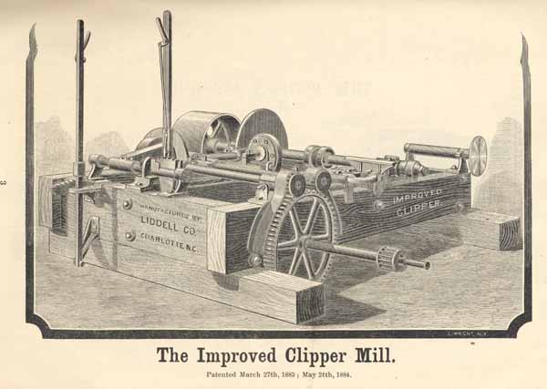
The Improved Clipper Mill.
Patented March 27th, 1883; May 24th, 1884.
Page 17
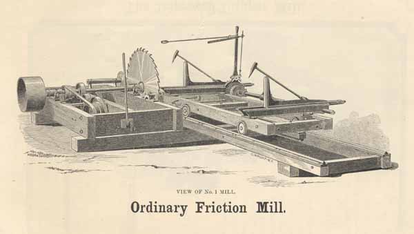
VIEW OF NO. 1 MILL.
Ordinary Friction Mill.
Page 18
Ordinary Friction Mills.
In addition to the variable feed mills shown on the foregoing pages, we also continue to build the ordinary friction mills with three changes of feed by means of a belt and cone pulleys. These mills are made strong and durable, some of them having been in use ten years. We make three sizes, the smallest being heavier than our variable feed Pony mill and the largest corresponding to our Standard No. 4 in size. Nos. 2 and 3 have all our latest improvements in the carriage, saw guide, head blocks and bulldogs, and No. 1 has the latest carriage and head blocks, but is not sent out with the bulldogs unless specially ordered, and at a slight advance on the list prices quoted.
Note carefully the specifications given below, which will give a correct idea of the sizes, both in relation to each other and to our mills of the variable feed type.
The cut on page 18 represents our No. 1 mill and that on page 20 our No. 3. The No. 2 mill is similar to the No. 3, except that it is smaller.
SPECIFICATIONS.
No. 1 Mill.--Husk 8 ft. long, 4 ft. 4 in. wide, 12 in. deep, and 4½ in. thick; mandrel 2 7/16in. diam., forged collar, pivoted adjustable arbor boxes, board roller, wheel spreader, and patent adjustable saw guide, two patent simultaneous and independent ratchet head blocks, and 17 ft. of connecting shaft, swage, gauge, monkey wrench, oil can and feed belt; driving pulley, 20 in. diam., 13 in. face, 24 ft. carriage, and 48 ft. of track on portable stringers; carriage 35½ in. wide, 4 in. thick, and 6½ in. deep; track 3¾ in. thick and 4¾ in. deep.
No. 2 Mill.--Husk, 9 ft. long, 4 ft., 4 in. wide, 12 in. deep and 4½ in. thick; mandrel, 211/16 in. diam., forged collar, pivoted adjustable arbor boxes, board roller, wheel spreader, patent adjustable saw guide; driving pulley, 20 in. diam. and 13 in. face; 24 ft. of carriage and 48 ft. of track on portable stringers; carriage, 35½ in. wide, 4 in. thick and 6½ in. deep; track, 3¾ in. thick and 4¾ in. deep; 2 patent simultaneous and independent ratchet head blocks, with patent bulldogs and 17 ft. of connecting shaft, swage, gauge, monkey wrench, cant hook, oil can and feed belt.
No. 3 Mill.--Husk, 9 ft. 6 in. long, 5 ft. 7 in. wide, 12 in. deep and 4½ in. thick; mandrel, 3 3/16 in. diam., forged collar, patent adjustable saw guide, pivoted adjustable arbor boxes, board roller, wheel spreader; 24 ft. carriage and 48 ft. of track on portable stringers; carriage, 37½ in. wide, 5 in. thick and 7 in. deep; track, 5 in. thick and 5 in. deep; 2 heavy patent simultaneous and independent ratchet head blocks, with bull dogs and 17 ft. of connecting shaft; swage, gauge, monkey wrench, cant hook, oil can and feed belt.
Page 19
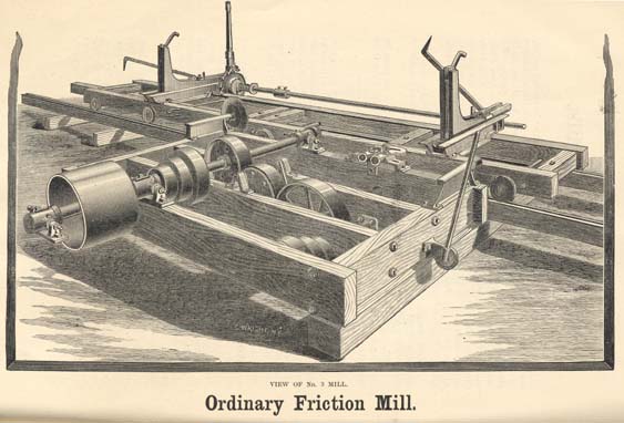
VIEW OF No. 3 MILL.
Ordinary Friction Mill.
Page 20
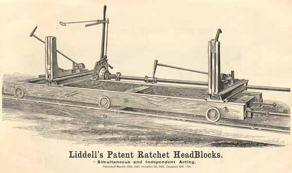
Liddell's Patent Ratchet HeadBlocks.
Simultaneous and Independent Acting.
Patented March 15th, 1881, October 2d, 1883, January 22d, 1884.
Page 21
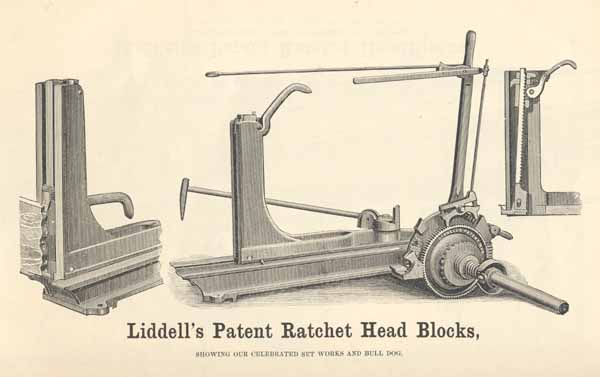
Liddell's Patent Ratchet Head Blocks,
SHOWING OUR CELEBRATED SET WORKS AND BULL DOG.
Page 22
Liddell's Patent Ratchet Head Blocks.
The cuts in this circular represent our well-known PATENT RATCHET HEAD BLOCK, in which we have recently made great improvements, and can establish for them superiority over all others for convenience and reliability. We call your attention to the following points:
First.--They are both Independent and Simultaneous Acting, operated by one Lever, and controlled by the Sawyer without change of position. By use of a double pawl and base attached to the upright lever the ratchet wheel is thrown back or forward at the will of the operator. By pressing the foot on a treadle, the Blocks become independent and remain so as long as the treadle is kept down. The moment the foot is removed the blocks again become simultaneous (as shown in the cut), the Clutch being thrown into gear by means of a Spring acting on one end against a collar and the other against the Clutch. Thus, without the slightest inconvenience, a tapering cut can be made whenever desired. The Clutch and Ratchet Wheel being indexed, the Sawyer can always tell when his Blocks are in line.
Second.--ANY SIZE OF LUMBER CAN BE CUT.--The throw of the Lever is easily adjusted, from one-eighth of an inch upward, and the operator once knowing the size of lumber to be sawed, can set the throw accordingly, and need not further regard the pointer.
Third.--The Swivel to which the log Dog is attached is so arranged that when not in use the Dog can be placed in any desired position and never falls in the way of the Saw, or interferes in any way with the operator.
Fourth.--OUR INDICATOR.--We furnish with these Head Blocks, when desired, at an extra cost, an Indicator to enable the Operator, if sawing boards, to tell at a glance what should be the thickness of the last or fourth slab in order to bring out the last piece to the same thickness as the rest of the stock. This device we believe to be the simplest and cheapest yet gotten up for the purpose.
Fifth.--OUR PATENT BULL DOG.--We call particular attention to our patent DOG for holding the last board or for clamping the timber after it is squared. At once strong and tenacious, we adopt the name given it by common consent of those using it, and it is now generally known as THE BULL DOG. A glance at the cut will show that in this Dog we have accomplished what has been sought by sawyers and manufacturers of saw mills, and on which the best inventive talent of the country has been employed for years, to wit: An Upper and Under Dog operated by one Lever. The sectional view of the knee of the Head Block with the Dog attached, shows the Dogs in the position they occupy when not in use, the lower having dropped below the level of the Block and the upper having receded back of the face of the Knee. The other cut of the Knee shows the Bull Dogs in use and holding the board. The Lever is so shaped that when raised up it pushes off of its rest the Carrier block. This, which has the Lever and Dog attached to it, drops down until the Dog comes in contact with the log. Pressure on the Lever drives the lower Dog in until the rack bar moves up the length of the slot, when the upper dog enters and the log is clamped as between the jaws of a vise. Raising the Lever loosens the Dogs, and the Carrier Block is raised up by a pull on the Lever to the top of the Knee, when it drops back out of the way of the log. It is simple, durable, and easily handled and surpasses in its efficiency and convenience anything yet gotten up for dogging timber.
Page 23
A Word About Our Presses.
Eleven years in the building of cotton presses, over 3,000 in use and to-day the largest manufacturers of this line of machinery in the United States, and perhaps in the world. These are facts which speak in stronger terms of the merits of our presses than anything else that could be said. Our success in this line, out of which all our other business has grown, is attributed to three facts: First, that the principle of our presses is that best adapted to the purpose; Second, that we give close attention to all of the details of the press, having in operation a system by which a duplicate part of any of our presses, furnished years ago, can be supplied promptly and with the assurance that it will fit its place without trouble; Thirdly, that we use in our presses the very best iron that can be bought, paying therefor from $5 to $7 per ton more than iron used for ordinary purposes, with a greater difference as against cheaper grades.
Starting with the Boss press, our line has gradually grown to meet the various wants of different sections of the country from Virginia to Texas, and the special requirements of planters large and small, until we are now actually making twelve different styles and sizes of presses. With this variety it would seem strange if we could not meet the wants of any planter.
We invite an examination of the cuts, descriptions and specifications which follow.
Page 24

The Boss Press.
VIEW OF CLOSED PRESS.
Page 25
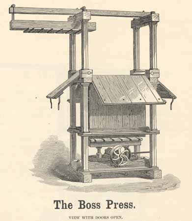
The Boss Press.
VIEW WITH DOORS OPEN.
Page 26
The Boss Press.
SPECIFICATIONS.
| Height over all | in feet, | 14 |
| Distance from bottom of Sill to bottom of Doors | in feet, | 7 |
| Length of wrought-iron screws | in feet, | 9 |
| Diameter of Screws | in inches, | 3¼ |
| Depth of Cotton Box | in feet, | 9 |
| Length of Cotton Box | in inches, | 54 |
| Width of Cotton Box | in inches, | 28 |
| Length of Column Rods | in feet, | 14 |
| Diameter of Column Rods | in inches, | 1 3/8 |
| Space required for Press when all doors are open | in feet, | 10½ × 11½ |
| Size of Pulley | in inches, | 20 × 6 |
| Usual number of revolutions of Pulley | 250 |
The Boss Press.
The "Boss" press has been on the market eleven years, and over 3,000 are now in successful operation throughout the entire cotton growing section, from Virginia to Texas. By its simplicity, durability, and the small amount of power required to operate it, it has won its way to popular favor with a rapidity unequaled by any similar machine now used.
In the construction of the "Boss" press we have been careful to maintain a correct proportion of weight to the strength required of the several parts, and to overcome mechanical inconveniences and difficulties which add to the work of the operator and make his task burdensome. There are no bolts or pins in the frame; it requires no mechanic to put it together, and any person, with the help of two or three laborers, can set it up in a few hours; and it can be taken down as often as desirable without injury.
Though apparently wooden, it is substantially an iron press. The columns are in halves, and are in three sections, being held together by cast flanges on the end, and a heavy iron rod passes through each from top to bottom of the press, the columns merely acting as slip collars. It has two heavy screws, made of 3¼-inch round steel, which work inside the box; and the follower block, being always parallel with the top or bottom block as the case may be, according as the press is made to pack up or down, an even bale is absolutely assured.
The power is applied by one belt, which runs all the time, a clutch attachment being so arranged that the gears are thrown out or the follower is made to move up or down at the pleasure of the operator.
Page 27

Boss Down Press.
SPECIFICATIONS.
| Height of Press over all | in feet, | 14½ |
| Distance from bottom of Sill to hinge of upper door | in feet, | 7¾ |
| Length of Wrought-iron Screws | in feet, | 9 2/3 |
| Diameter of Wrought-iron Screws | in inches, | 2¼ |
| Depth of Cotton Box | in feet, | 8½ |
| Length of Cotton Box | in inches, | 54 |
| Width of Cotton Box | in inches, | 28 |
| Length of Column Rods | in feet, | 14½ |
| Diameter of Column Rods | in inches, | 1 3/8 |
| Space required for Press, when all doors are open | in feet, | 10½ × 11½ |
| Size of large Pulley | in inches, | 20 × 6 |
| Size of small Pulley | in inches, | 12 × 6 |
| Usual number of revolutions of large Pulley | 225 | |
| Usual number of revolutions of small Pulley | 375 |
Page 28
The Boss Down Press
Experience has proven that our No. 2 Boss press is best adapted to down packing. Heretofore we have sent it out the same as the up-packing press turned upside down. This season we present to our trade a down packing press built on the No. 2 press principle with the following additions and advantages, which must place it in the front rank of down packing presses:
1st--A bed plate resting on a solid platform instead of being divided between two sills.
2d--A top door opening to the line of the gin floor that the cotton may be shoved into the box directly from the gin.
3d--Two pulleys of different sizes with a clutch between them, the one being small to permit of the follower being run down one or more times on the cotton at a high speed, and the other of sufficient size to give proper power to press the bale; thus giving a self-tramping press and saving the expense of a tramper in the box.
4th--Door fastenings (same as on our Single Screw Boss) which may be unloosed with the movement of one lever, and which free all the doors at once, the fastenings being left swinging in the positions they occupy when the doors are closed, and thus are easily hooked together.
5th--A simple trip for automatically throwing the press out of gear both when the follower runs down on the bale and when it runs up. This trip is readily adjustable, and, therefore, can be set to make a bale of any size within the capacity of the press.
Page 29
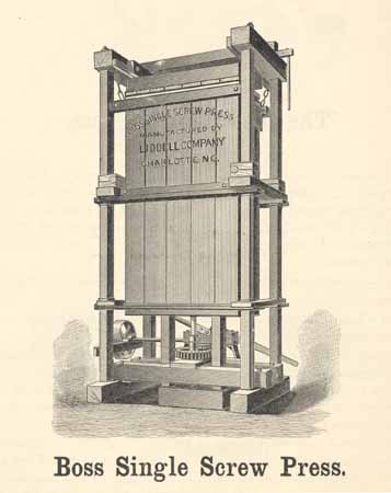
Boss Single Screw Press.
Boss Single Screw Press.
| Height over all | in feet, | 14 |
| Distance from bottom of Sill to bottom of Doors | in feet, | 7¾ |
| Length of wrought iron Screw | in feet, | 10 |
| Diameter of Screw | in inches, | 2¾ |
| Depth of Cotton Box | in feet, | 9 |
| Length of Cotton Box | in inches, | 54 |
| Width of Cotton Box | in inches, | 28 |
| Length of Column Rods | in feet, | 14 |
| Diameter of Column Rods | in inches, | 1¼ |
| Space required for Press when all doors are open | in feet, | 10½×11¼ |
| Size of Pulley | in inches, | 20×6 |
| Usual number of revolutions of Pulley | 250 |
Page 30
Boss Single Screw Press.
In this press we have endeavored to meet every requirement of the baler and at a price at which it is impossible to furnish any of our double screw presses. In its main features the frame is the same as the Boss and No. 2, but the method of moving the follower is different, as is also the door clamps. The latter are unloosed at once by a pull on the handle hanging down near the corner, as shown in the cut. The doors are thus opened, not only with one movement of a lever, but each one is unfastened at the same instant, a feature which saves time and prevents the chance of the clamps binding on one set of doors from the spring of the cotton after the other set has been unfastened.
The top block being run out on rollers to the side of the press, gives the tramper the advantage of standing upright in the box when it is nearly full of cotton, the timbers on top to hold the press together being to one side of the box.
The gearing on this press and the principle of its operation is the same as the Boss No. 2, with the difference that only one screw is used. This screw pulls as in the Boss No. 2, and the upright timbers do the pushing. These timbers being set in the follower near its ends, insures an even bale and prevents the creening complained of in single screw presses.
It will be observed also that in this press the power is applied at the end of the press, which is claimed by many users as an advantage, enabling them to set the press with the side toward the gin so that the cotton can be pushed directly from the condenser into the baling box.
Page 31
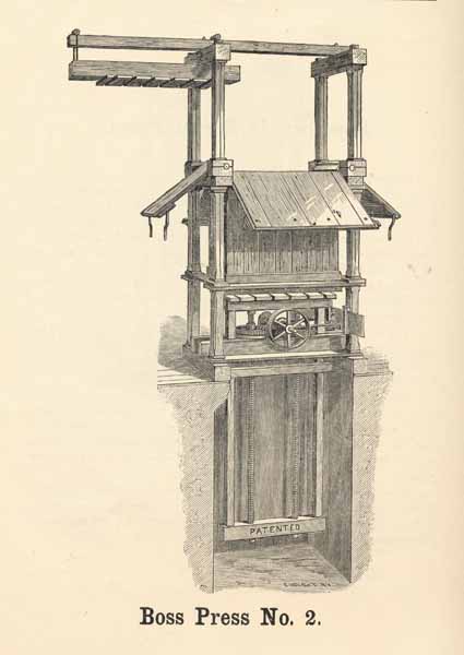
Boss Press No. 2.
Page 32
The Boss Press No. 2.
The frame of this press is identical with that of the Boss. A superficial examination of the two presses, standing side by side in operation, would show no difference between them; but upon a more careful examination of the Boss No. 2, the two screws inside the box would be seen to be pulling instead of pushing. In this press we employ the tensile strength of the screws, by pulling up the cross piece, shown in the cut at the lower end of the screws, which itself pushes up the follower blocks by means of the upright timbers at the sides of the screws. These two pieces, pushing with equal force on the follower at its extremities, insure a perfectly rigid motion of the follower, and consequently an even bale. The gearing of this press, as in the Boss, rests in a solid bed-plate, and is, therefore, not subject to such variations as may occur from the shrinkage of the timbers. Like the Boss Press, the Boss No. 2 is adapted to any kind of power, and has given perfect satisfaction under all circumstances. The principle on which this press is built, enabling us to make it lighter and sell it cheaper than the Boss Press, is that wrought iron will stand a strain of thirty-four tons per square inch when applied as in this press. When applied as in other presses, it will stand a load of only sixteen tons per square inch, this being the difference between tensile and compressing strain.
SPECIFICATIONS.
| Height over all | in feet, | 14 |
| Distance from bottom of Sill to bottom of Doors | in feet, | 7¾ |
| Length of Wrought Iron Screws | in feet, | 9 2/3 |
| Diameter of Screws | in inches, | 2¼ |
| Depth of Cotton Box | in feet, | 9 |
| Length of Cotton Box | in inches, | 54 |
| Width of Cotton Box | in inches, | 28 |
| Length of Column Rods | in feet, | 14 |
| Diameter of Column Rods | in inches, | 1¼ |
| Space required for Press when all doors are open | in feet, | 10½×11½ |
| Size of Pulley | in inches, | 20×6 |
| Usual number of revolutions of Pulley | 250 |
Page 33
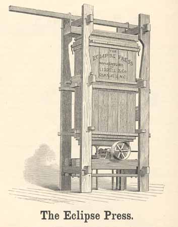
The Eclipse Press.
Page 34
The Eclipse Press.
SPECIFICATIONS.
| Height of Press over all | in feet, | 16⅓ |
| Distance from bottom of Sill to top of Box | in feet, | 12 |
| Length of Wrought-iron Screws | in feet, | 9 2/3 |
| Diameter of Wrought-iron Screws | in inches, | 2¼ |
| Depth of Cotton Box | in feet, | 9 |
| Length of Cotton Box | in inches, | 54 |
| Width of Cotton Box | in inches, | 28 |
| Space required for Press when all doors are open | in feet, | 10½ × 11½ |
| Size of Pulley | in inches, | 20 × 6 |
| Usual number of revolutions of Pulley | 250 |
The Eclipse Press.
In the Eclipse Press we present the strongest possible wooden framed Press. The structure is designed to utilize the entire strength of the wood, and will stand the greatest strain that such a frame can be made to resist. The working principle of this Press is the same as the "Boss No. 2," and in fact it is the same Press with solid wooden columns instead of the iron rods surrounded by wood.
We do not recommend or approve of a wooden framed Press. We manufacture them only to meet the competitive prices of other manufacturers who do not use the iron frame. In every case it is advisable to pay the slight difference in the price and get an iron frame Press, but if a wooden frame is desired we offer the Eclipse as the best.
Page 35
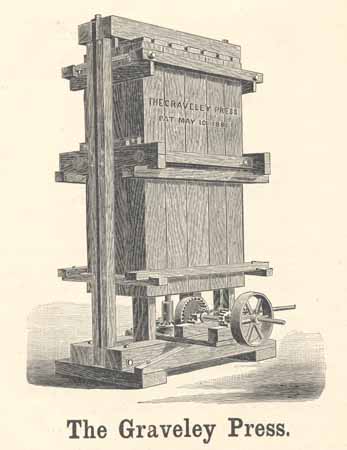
The Graveley Press.
Page 36
Description of Graveley Press.
SPECIFICATIONS.
| Height over all | in feet, | 14 |
| Distance from bottom of Sill to bottom of Doors | in feet, | 8 |
| Length of Wrought-iron Screw | in feet, | 10 |
| Diameter of Screws | in inches, | 2½ |
| Depth of Cotton Box | in feet, | 9 |
| Length of Cotton Box | in inches, | 54 |
| Width of Cotton Box | in inches, | 28 |
| Length of Column Rods | in feet, | 13½ |
| Diameter of Column Rods | in inches, | 1½ |
| Space required for Press when doors are open | in feet, | 7×10 |
| Size of Pulley | in inches, | 20×6 |
| Usual number of revolutions of Pulley | 250 |
Description of Graveley Press.
Where parties desire a cheaper press than any of the Boss presses, we recommend the Graveley. It is operated entirely by gearing, and there are no ropes to break, and no complicated machinery to be continually needing repairs.
Every part has been carefully proportioned to give the requisite strength, without unnecessary weight, and in presenting the Graveley press to the public, we are able to offer what has long been needed--namely, a first-class screw press, for steam power, which can be sold complete, at about the same price as is charged for the numerous unsatisfactory combinations of ropes, pulleys, levers, and cogs, which have, in many cases, but little to recommend them except the low price at which they are sold.
The bale is delivered at the top of press. There are heavy iron rods at each side of the press, between the wooden uprights, making this substantially what is known as an iron frame press.
To fill the packing box, the rod is moved away from the top follower block an inch or two, which enables the block to be swung around on the rod at the other side, thus giving free and easy access to the packing box.
Power is applied by one belt, which runs all the time, and the follower is allowed to run up, or down, or remain stationary by means of a clutch attachment operating suitable gearing.
The manner of applying the power in this press is the same as that employed in the Boss No. 2, previously described, the tensile strength of the screw being used.
Page 37

The Liddell Hand Press.
Page 38
Description of Hand Press.
There are a great many farmers who cannot advantageously use our Steam Power Press, yet want a press that will do their work satisfactorily, which can be purchased at a small outlay. Our Hand Press is designed to supply this demand, and the gratifying reception it has received at the hands of those who have used them proves to us that we have "filled a long felt want" by putting this press on the market.
The height of the box is 7 feet. Size of bale 60 inches long, 28 inches wide, and 30 inches deep. The bale comes out at the bottom.
This is a substantial press, made with wood frame, and strong enough to pack any ordinary sized bale.
At each end of the press is a 2¼ inch wrought iron screw, the pulling strength of which is used in the operation of packing. The nut forms a crown wheel, geared to the shaft on which is attached the "spider" as shown. All the gearing is enclosed in a cast iron case, which prevents it from clogging with cotton, etc., and enables us to make heavy bearings for the shaft and nut, giving all necessary strength
The follower block is strengthened by two iron bars, extending the whole way across, and having holes drilled in each end; corresponding with these holes are eyes in the upper end of each screw, through which is inserted a pin, which firmly connects the screws to the follower.
It will be observed that the frame at one end is considerably higher than at the other, and that the irons of the follower project considerably at the higher end, and are engaged in a hook attached to the frame. When it is desired to put cotton in the press the pin is taken out, at the end which has not the hook, while the screw at the end provided with the hook is turned upward, raising the follower block to the position as shown in engraving. When the cotton is ready to be packed, lower the screw, until the follower can be again attached to the screw at the other end, put in the pin and the press is ready to pack.
These presses are especially adapted to mounting on wheels, the two bottom sills constituting the connection between the wheels. The press is ready to pack as soon as stopped without any changes. We furnish these presses as shown in the cut, or mounted on substantial wheels, the extra cost for mounting being $50.
Page 39
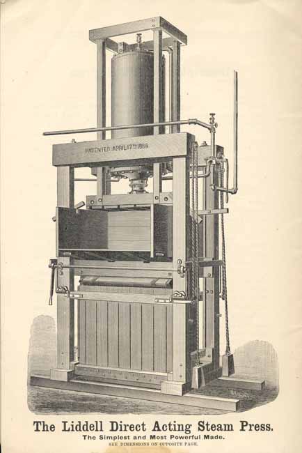
The Liddell Direct Acting Steam Press.
The Simplest and Most Powerful Made.
SEE DIMENSIONS ON OPPOSITE PAGE.
Page 40
Direct Acting Steam Presses.
As the advantages of a direct acting steam press will at once appear to any one acquainted with the baling of cotton, we desire merely to call attention to some special claims we make for the press shown in the cut on opposite page:
1st. A cylinder above the press allowing the follower to be run down on the cotton as often as may be desired, dispensing with tramping.
2d. A cotton box with door plank notched to hold the cotton from springing back, and an additional simple, self-acting eccentric to aid in this operation.
3d. Substantial press frame supported at the four corners by strong iron rods.
4th. A set of door fastenings which permits all doors to be opened at once and by one lever.
5th. Balanced doors to prevent their falling heavily to the floor when opened, and to relieve the severe strain of lifting them to their places.
6th. A valve held to its seat by the natural pressure of the steam, and not, therefore, subject to the rapid wear of any valve in the shape of a plug cock.
7th. Complete adaptability to one or two story gin houses.
8th. Requiring no pit for its operation, thereby saving the annoyance which arises from this cause in low countries.
9th. A cylinder of 30 inches diameter, giving an area of steam pressure one-third larger than any other steam press built, and requiring, therefore, one-third less pressure of steam in boiler.
10th. Another size cylinder, 26½ inches in diameter, but still larger than any other heretofore offered, for those who for special reasons may require high pressure of steam in their boilers any way, and who can thereby save something in the first cost.
11th. The successful operation of this press under the severest tests to which presses for baling cotton will be subjected, and the removal of every seeming objection to their complete adaptability to baling purposes.
Finally, a strict attention to those smaller details in the construction of the press throughout, which our experience in the building of over three thousand presses for baling cotton, warps, etc., and the knowledge gained thereby, has enabled us to give this press.
We, therefore, present this press to the trade confident that it is without a peer in the market to-day.
DIMENSIONS.
| Height | in feet, | 15½ |
| Depth of Cotton Box | in feet, | 7 |
| Length of Cotton Box | in inches, | 54 |
| Width of Cotton Box | in inches, | 28 |
| Space required when all doors are open | in feet, | 11×12 |
| Diameter of cylinder on No. 1 press | in inches, | 30 |
| Diameter of cylinder on No. 2 press | in inches, | 26½ |
| Size of four column rods | in inches, | 1½ |
| Size of pipe connections | in inches, | 1½ |
Page 41
The working principle of this press is the same as that of our No. 2 Boss Cotton Press, so well and favorably known throughout the cotton belt. This principle consists in the use of the tensile or pulling strength of the screws, the ratio of which to the pushing strength is as thirty-four to sixteen. The superior strength of this press will therefore at once appear, and our experience of the special strains required in baling has enabled us to give to it throughout a proportionate strength which no amount of theoretical figuring could establish. In appearance it is the most attractive press we build.
The pulley can be driven from the main shaft, the press being moved up or down or allowed to run idle by means of a direct and positive clutch arrangement, which has been successfully tested on all our presses. When it is desired to use the open press the doors and box can be easily removed without disturbing the other parts, and extra platens are furnished for the open bales.
A list of cotton factories using this press will be furnished on application.
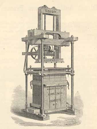
SPECIFICATIONS
| Height over all | in feet, | 9½ |
| Depth of Box | in feet, | 4½ |
| Length of Box | in feet, | 3 |
| Width of Box | in feet, | 2 |
| Size of Pulley | in inches, | 20×6 |
| Usual number of revolutions of Pulley | 200 |
Page 42
Liddell's
Patent Doubly Adjustable Hanger.
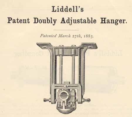
Patented March 27th, 1883.
The above cut represents a hanger which for convenience of adjustment and strength, will be found to meet all requirements, and to possess advantages over all other adjustable hangers. Its production is the result of thirty years' experience in lining shafts for cotton mills and other high-speed machinery, and attention has been given to all details, so as to cause the least possible delay and annoyance in lining and keeping in line.
IN THE FIRST PLACE, the weight of the shaft is suspended on wrought iron bolts, an advantage which will at once appear, these bolts constituting the means of adjustment up and down; and the heads of the bolts drop into sockets to prevent their turning when the nuts is turned on the bottom.
SECOND.--The horizontal adjustment is affected by means of set screws, working against the box, so that an adjustment of nearly two inches, horizontally or perpendicularly, can be quickly made by one man with a wrench.
THIRD.--In taking down the shaft, for putting on additional pulleys, or for any other purpose, the lower part of the bearing can be easily taken off and the shaft dropped down (the upper half being held in position by the set screws shown in cut), and in the same way raised into its position without the trouble of lifting it first up and out of its bearings, then horizontally to clear the hanger and then lowering it, going through the same difficult process in placing the shaft in position again.
FOURTH.--To avoid a possibility of the nuts on the swing bolts working down, ears have been attached to the drip cup in such a manner as to enclose these nuts and thus effectually prevent their turning.
FIFTH.--To insure the drip cup remaining in position (without tightly driving in pins, which would cause trouble every time they had to be removed), the pins are made with eyes, being bent at right angles near the eye, and fitted loosely in the holes; the eye part drops down by its own weight on the inside of the drip cup, thus constituting a complete lock for it.
Page 43
Liddell's Patent Shaft Coupling.

PATENTED MARCH 27th, 1883.
To obtain a shaft coupling which would overcome all objections, and at the same time cost less than the expensive couplings in general use, has been the object of manufacturers for many years, and a want keenly felt by those running machinery. The coupling shown above fills this want, and at the same time the further demand for convenience, an important element, as it is frequently desired to uncouple a shaft for changing pulleys or other purposes.
The common form of sleeve coupling is used in a great many instances for its cheapness and convenience, but is dangerous on account of the projecting heads of set screws. In this coupling the set screws are entirely covered by a shield. In the cut this shield is detached, showing how it may be slipped off and on, being held in position by two cap screws, running into the flange of the inner sleeve.
When the full power of the shaft is needed, the coupling with key is thoroughly effective, while retaining all the convenience referred to. This key is held firmly in position by means of the two set screws shown, while the other four afford an additional safeguard and also prevent any endwise movement of the shaft. We furnish these couplings either with or without keys, as may be ordered, and at a different price.
It may be added that these couplings can be and are frequently used for pulleys where they happen to be in the right position for this purpose.
Return to Menu Page for Liddell Company, Manufacturers by Liddell and Co. (Charlotte, N.C.)
Return to The North Carolina Experience Home Page
Return to Documenting the American South Home Page